>Input Voltage:10V ~ 16V
>Power:< 2.5W
>Connection Interface:RS485/Bluetooth
Brand:
S4AItem NO.:
ITS-AX279G millimeter wave radar detection systems
Model No.: ITS-AX2
Operating frequency | 79GHz |
Operating voltage | 12V |
Signal output | Switching |
Humidity range | 25°C relative humidity 98% |
Detection range | 1m~6m (distance adjustable) |
Average power consumption | <2.5W |
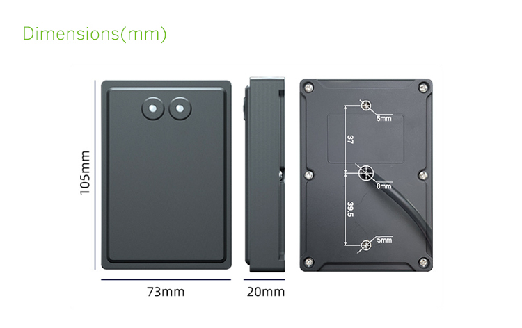
Dimensions | 105x73x20(mm) |
Operating temperature | -40°C - 85°C |
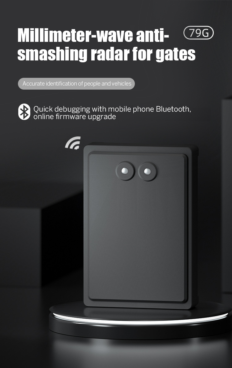
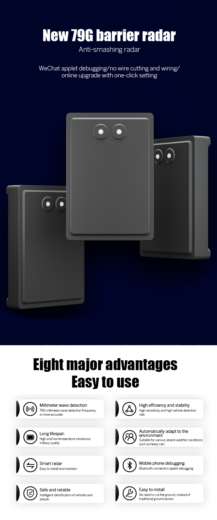
This barrier anti-smashing radar adopts 79G millimeter wave detection technology, with stronger performance and added Bluetooth applet debugging function.
It is simpler than the previous radar debugging method and can save users' learning time cost to the greatest extent; it does not need to cut the road surface,
and is easy to install. It can distinguish cars and people through the difference in radar reflection intensity, and can prevent the occurrence of "smashing people"
and "smashing cars"; it can automatically identify the background according to the reflected wave and effectively filter out the false triggering target;
it has strong environmental adaptability and excellent detection performance, and is not affected by external environment such as light, dust, rain and snow.
Less manpower and shorter construction period can reduce construction and maintenance costs.


Radar installation method
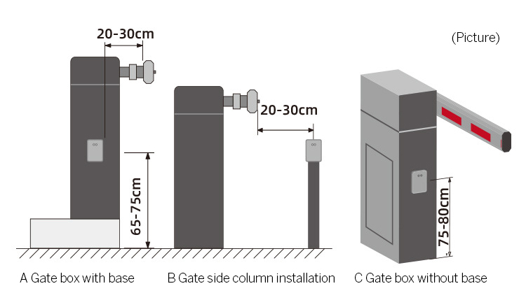
The radar is installed on the gate box or independent column perpendicular to the lane (vehicle in and out) direction. The installation process is as follows:
1. The inner side of the gate pole is 20-30cm away from the radar installation hole; radar installation height: the car is installed between 65-75cm from the ground of the lane; the large car (chassis higher than 70cm) is installed between 75-80cm. As shown in the figure below.
2. The gate chassis must be firmly fixed to prevent the chassis from shaking when the gate is working.
3. Within the radar detection distance, there must be no obstacles except the gate pole, such as road cones, metal manhole covers, isolation fences, signboards, etc.
4. The schematic diagram of the gate radar installation specification is as follows:
As shown in the figure below, first determine the installation position, then punch a threading hole and 2 fixing holes on the box. (Positioning hole self-adhesive stickers and fixing screws are provided in the product packaging), then fix the radar on the box and tighten the fixing screws.
